
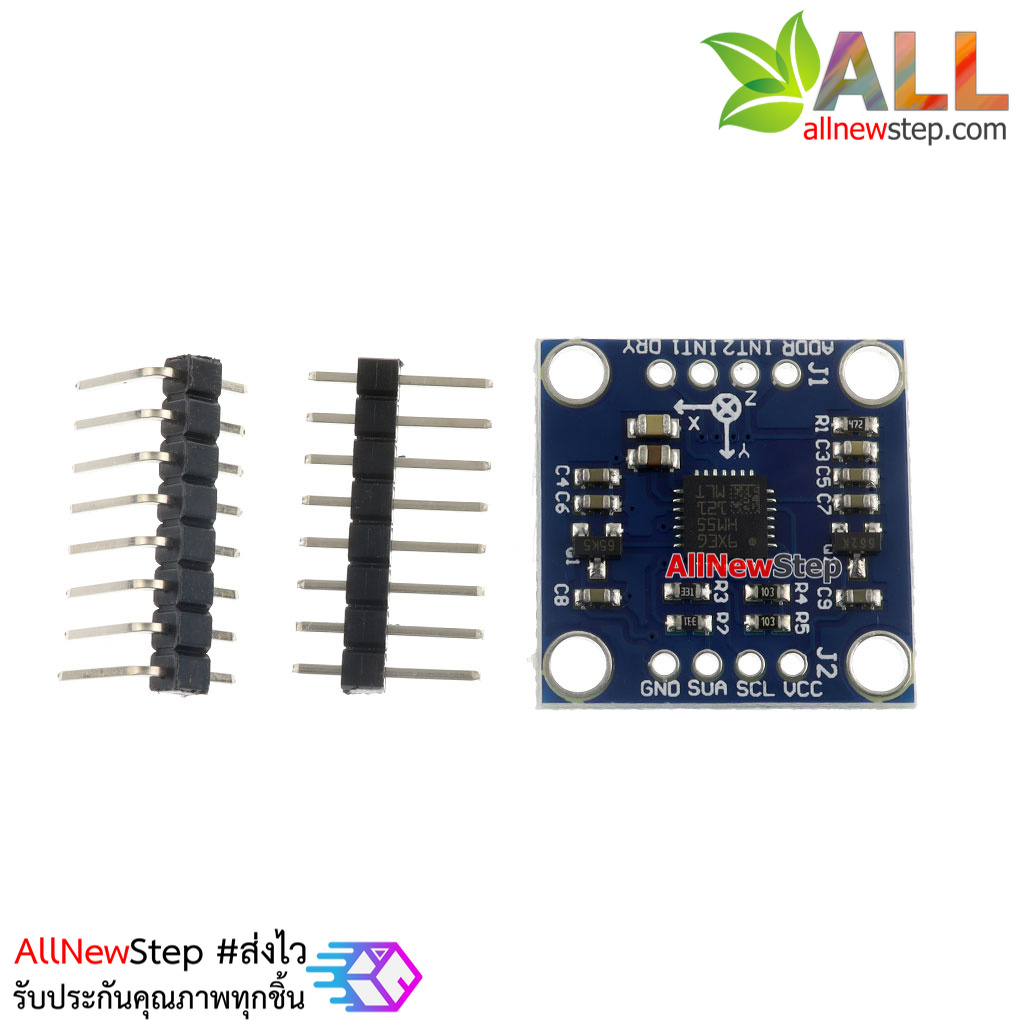
LSM303DLH L3G4200 Module for Arduino


| รหัสสินค้า | A3050 |
| หมวดหมู่ | เซนเซอร์ความเร่ง / ไจโร / IMU |
| ราคา | 180.00 บาท |
| สถานะสินค้า | พร้อมส่ง |
| จำนวน | ชิ้น |

รายละเอียดสินค้า
- Power supply: 3-5v (internal low dropout voltage regulator)
- Communication method: standard IIC communication protocol
- Magnetic field range:
- ± 1.3 / ± 1.9 / ± 2.5 / ± 4.0 / ± 4.7 /
- ± 5.6 / ± 8.1 gauss
- Acceleration range: ± 2 g / ± 4 g / ± 8 g
- ± 1.3 / ± 1.9 / ± 2.5 / ± 4.0 / ± 4.7 /
วิธีการชำระเงิน
ขาย Arduino ,ซื้อ Arduino มั่นใจ AllNewStep
ซื้อ Arduino กับ AllNewStep ขาย Arduino ตลอด 24 ชั่วโมง มั่นใจได้ 100% เราจัดส่งสินค้าทางไปรษณีย์ แบบ EMS / Best Express
แพ็คสินค้าอย่างดีปลอดภัย ส่งถึงมือลูกค้าอย่างแน่นอน
-
-
-
-
-
-
- ถ้าทำรายการสั่งซื้อสำเร็จ = มีของพร้อมส่ง ทางร้านจองสินค้าไว้ให้ 3 วัน
-
-
-
-
-
จัดส่ง วันอาทิตย์-วันศุกร์
ส่งแบบ EMS ได้รับ 1-2 วัน นับจากวันจัดส่ง
วันจันทร์-ศุกร์ แจ้งโอนก่อน 14.00 น. จัดส่งวันนั้น
แจ้งโอนวันศุกร์ หลัง 14.00 น. และวันเสาร์ จัดส่งวันอาทิตย์
แจ้งโอนวันอาทิตย์ จัดส่งวันจันทร์
ขาย Arduino การตรวจสอบเลขแทรคสินค้า Arduino
- เมื่อจัดส่งแล้วทางร้านแจ้งเลขแทรคไปให้ทาง E-Mail ที่แจ้งไว้ตอนทำรายการสั่งซื้อ

ขาย Arduino ใบกำกับภาษี
ขาย Arduino สินค้าทุกชิ้นที่ซื้อกับทางร้าน AllNewStep
สามารถนำไปเบิกกับ หน่วยงานราชการ บริษัท ห้างร้าน ได้อย่างถูกต้อง จึงซื้อได้อย่างมั่นใจ
กรณีที่ไม่ได้นำไปใช้เบิก
สามารถติ๊กออก ข้ามช่องนี้ไม่ต้องกรอกได้ ทางร้านออกเป็น ใบเสร็จรับเงิน / ใบกำกับภาษีฉบับย่อให้ แนบไปพร้อมกับสินค้า
ขาย Arduino ใบกำกับภาษีเต็มรูปแบบ
สำคัญมาก "ข้อมูลใบกำกับภาษีไม่สามารถเปลี่ยนแปลงหรือแก้ไขได้หลังการสั่งซื้อสินค้า"
ขาย Arduino ทางร้าน AllNewStep ออกใบกำกับภาษี/ใบเสร็จรับเงิน ลงวันที่ ที่แจ้งชำระสินค้าให้ลูกค้าทุกครั้งที่ทำรายการสั่งซื้อโดยแนบไปพร้อมสินค้า
ขาย Arduino ข้อมูลสำหรับออกใบกำกับภาษี
ขาย Arduino โปรดตรวจสอบข้อมูลเหล่านี้ให้ชัดเจน ก่อนกรอกข้อมูล เพราะใบกำกับภาษีไม่สามารถเปลี่ยนแปลง หรือแก้ไขได้หลังซื้อสินค้า
- ชื่อสถานประกอบการเช่นสถานศึกษาบริษัทห้างร้าน
- ที่อยู่สถานประกอบการ
- เลขที่ประจำตัวผู้เสียภาษี
- สาขา
*** สำคัญมาก :: ข้อมูลจะต้องมีครบทั้ง 4 อย่างนี้ ถ้าไม่ครบ ทางร้านจำเป็นต้องออกใบกำกับภาษีอย่างย่อ เนื่องจากข้อมูลไม่ครบ
ขาย Arduino วิธีการชำระเงิน
ชำระเงินผ่านธนาคาร เรามีหลายธนาคารให้เลือก ขาย Arduino เพื่ออำนวยความสะดวกให้กับลูกค้า
การทำธุรกรรมของธนาคารต่างสาขาหรือต่างธนาคาร จะมีค่าธรรมเนียมเพิ่ม แล้วแต่ธนาคาร กรณีมีค่าธรรมเนียมรายได้เป็นของธนาคาร ทางร้านไม่ได้ออกค่าธรรมเนียมให้
ถ้าทำธุรกรรมภายในธนาคารเดียวกัน จะเสียค่าธรรมเนียมน้อยที่สุดหรือไม่เสียเลย บางธนาคารจะไม่คิดค่าธรรมเนียมโดยจำกัดว่าฟรีได้กี่ครั้งใน 1 เดือน เช่นฟรีค่าธรรมเนียมเมื่อโอนในธนาคารเดียวกัน 5 ครั้ง/เดือน ผ่านทางตู้ ATM
ดังนั้น ควรเลือกโอนมาที่ธนาคารเดียวกัน จะเสียค่าธรรมเนียมน้อยที่สุดหรือไม่เสียค่าธรรมเนียมตามเงื่อนไขที่ธนาคารกำหนด
ขาย Arduino เมื่อชำระเงินผ่านธนาคารแล้ว
กรุณาแจ้งที่หน้า แจ้งชำระเงิน https://www.allnewstep.com/informpayment
พร้อมแนบสลิป หรือภาพหน้าจอการโอนที่สำเร็จแล้ว ด้วยทุกครั้ง
เพื่อเป็นหลักฐาน และเก็บสลิปหลักฐานการโอนเงินไว้จนกว่าจะได้รับสินค้า
กรณีที่ธนาคารสลิปหมด หรือไม่มีสลิป สามารถแจ้งข้อความ รายละเอียดการโอนเงินได้ที่ เมนู ติดต่อ AllNewStep https://www.allnewstep.com/contactus ทางร้านจะดำเนินการตรวจสอบและรีบจัดส่งให้เร็วที่สุด
แนะนำจ่ายเงินผ่าน PromtPay ฟรีค่าธรรมเนียม หรือน้อยที่สุด Recomment
สแกน QR Code นี่จ่ายได้เลย
ขาย Arduino AllNewStep มีอุปกรณ์สำหรับ Arduio ครบทุกอย่างที่อยากได้ จากทุกแห่งทั่วโลก ในราคาที่ถูกที่สุด รับประกันคุณภาพ เสียเปลี่ยนตัวใหม่ให้ทันที ไม่ต้องรอ ไม่ต้องเสียค่าส่งสินค้ามาเคลม ขาย Arduino ตามรายละเอียดการรับประกันด้านล่างนี้

สินค้าทุกชิ้นมีรับประกัน 30 วัน ซื้อสินค้าจาก AllNewStep มั่นใจได้ รับประกันคุณภาพ ด้วยการมีประกันสินค้าที่ดีกว่าเราได้ตรวจเช็คและรับประกันสินค้าซื้อไปใช้ได้อย่างมั่นใจและสบายใจ เพื่อให้ลูกค้าถูกใจที่สุด
ทั้ง นี้หากมีสินค้าที่ได้รับมีความผิดพลาดอันใด ที่อาจเกิดขึ้นได้ ไม่ว่าจะเป็นอุปกรณ์เสีย หรือความเสียหายระหว่างการส่ง โดยที่ลูกค้าไม่ได้เป็นคนกระทำ AllNewStep รับประกันเปลี่ยนตัวใหม่ให้ทันที ภายใน 30 วันหลังจากได้รับสินค้า พร้อมออกค่าส่งสินค้าให้ ทั้งค่าส่งมา และค่าส่งกลับ ลูกค้าไม่ต้องรับภาระเรื่องค่าจัดส่ง โดยสามารถใช้กล่องเดิมส่งมาได้ โดยมีเงื่อนไขดังนี้
- ขาย Arduino การซื้อสินค้า ถือว่าลูกค้ายินยอมและปฎิบัติตามเงื่อนไขและการรับประกันของทางร้านแล้ว กรณีไม่ตรงตามเงื่อนไข ทางร้านขอสงวนสิทธิ์ในการรับประกันสินค้า
- ขาย Arduino คำแนะนำจากทางร้านเป็นเพียงข้อมูลบางส่วน อาจมีข้อมูลหรือเนื้อหาไม่ครบถ้วนทุกประเด็น ไม่สามารถใช้อ้างอิงได้ โปรดศึกษาข้อมูลเพิ่มเติมประกอบการพิจารณา
- ขาย Arduino สินค้าอ้างอิงตามวงจรและสเปค ทางร้านรับประกันการทำงานถูกต้องทุกชิ้น
- ขาย Arduino การสรีนสี/ข้อความ/สีของบอร์ด/อาจมีแต่ต่างบ้าง ไม่มีผลกับการใช้งาน ทางร้านขอสงวนสิทธิ์ในการรับประกันการสกรีน/สีของบอร์ด อาจมีความแต่ต่างบ้าง ซึ่งไม่มีผลกับการใช้งาน
- การแจ้งรายละเอียดทาง sms ทางร้านอาจไม่ได้รับหรือตรวจสอบได้ล่าช้า เพื่อความรวดเร็วและไม่ผิดพลาด จึงขอยกเว้นช่องทาง sms
- การสั่งซื้อจะสมบูรณ์เมื่อลูกค้าชำระเงินและได้รับใบเสร็จของทางร้านแล้ว ซึ่งสามารถนำมาใช้เป็นหลักฐานได้
- สินค้า ต้องเขียนรายละเอียดปัญหาแนบมาด้วย ส่งมาพร้อมใบเสร็จรับเงินหรือสำเนาใบเสร็จรับเงิน จาก AllNewStep มาในกล่องด้วย เพื่อเป็นหลักฐาน สำคัญมาก กรณีที่ไม่มีหลักฐานใบเสร็จของทางร้าน ขอสงวนสิทธิ์เนื่องจากไม่ตรงตามเงื่อนไขการรับประกัน
- สินค้าจะต้องเป็นความเสียหายที่เกิดจากตัวอุปกรณ์ ไม่ใช่ความเสียหายที่เกิดจากการใช้งานของตัวลูกค้าเอง เช่น อุปกรณ์ 3.3V แต่จ่ายไฟ 5V การจ่ายไฟเกินทำให้อุปกรณ์เสียหายได้
- สินค้าต้องอยู่ในสภาพที่สมบูรณ์เช่น ไม่มีรอยไหม้ แตกหัก ไม่มีรอยงัดแงะ หรืออื่น ๆ
- ความเสียหายที่เกิดขึ้นต้องไม่เกิดจากใช้งานผิดประเภท ดัดแปลง แก้ไข หรือใส่ไฟผิดขั้ว
- อุปกรณ์ประเภทเซอร์เฟสเมาส์ SMD การบัดกรีมีความเสียงต่ออุปกรณ์เสียหาย ทางร้านขอยกเว้นการรับประกันอุปกรณ์ประเภทนี้
- การรับประกันเฉพาะ hardware ไม่รวมการอัพเกรด software/firmware ของตัวอุปกรณ์
- การรับประกัน จะพิจารณาจากข้อเท็จจริง ขึ้นอยู่กับทาง AllNewStep
- การรับประกันเปลี่ยนอุปกรณ์ใหม่ AllNewStep รับประกันสินค้าทุกชิ้นที่ขายในร้าน โดยร้านเป็นผู้รับผิดชอบความเสียหายเอง
- การรับประกัน นี้ อาจเป็นการเปลี่ยนสินค้าใหม่ หรือ คืนเงิน ขึ้นอยู่กับ AllNewStep พิจารณา ครอบคลุมทั้งตัวสินค้าและค่าจัดส่งทุกอย่าง ยกเว้นค่าใช้จ่ายอื่น ๆ นอกเหนือจากนี้ เช่น ค่าเสียเวลา ค่าปรับที่เกิดขึ้นทั้งหมด
- ทางร้านมีสิทธิ์ยกเลิกหรือคืนเงินในรายการสั่งซื้อให้ลูกค้าได้
- ถ้าสินค้าที่ส่งมามีปัญหาทั้งหมดทุกชิ้น AllNewStep จะแนบค่าส่งตอนที่ส่งมาคืนให้ในกล่อง และออกค่าส่งกลับส่งไปให้ลูกค้า ลูกค้าไม่ต้องรับภาระเรื่องค่าจัดส่ง
- ถ้าส่งมามีอย่างน้อย 1 ชิ้นที่ไม่มีปัญหา ทางร้านออกค่าส่งกลับให้ฟรี แต่ไม่ได้ออกค่าส่งให้ โปรดตรวจสอบให้ละเอียด
- ถ้าไม่มีชิ้นไหนมีปัญหาเลยทางร้านไม่ได้ออกค่าส่งให้ โปรดตรวจสอบให้ละเอียด
- การ นับวัน หากสินค้าถึงมือลูกค้าในวันที่ 1/5/2564 ( ตรวจสอบได้จากไปรษณีย์ไทย) เมื่อพบความเสียหาย ลูกค้าจะต้องส่งสินค้ากลับคืนมาที่ AllNewStep ภายในวันที่ 31/5/2564 โดยอ้างอิงจากเลขแทรค ผ่านไปรษณีย์ลงทะเบียน หรือแบบ EMS ถ้ามีเลือกบริการเสริมพิเศษนอกเหนือจากวิธีส่งปกติ เช่น ค่าบริการพิเศษ พกง. ลูกค้าเป็นออกค่าบริการพิเศษนี้เอง
- กรณีสินค้าไม่มีปัญหา ทางร้านขอไม่รับคืนหรือเปลี่ยนสินค้า โปรดพิจารณาตรวจสอบให้ละเอียดก่อนสั่งซื้อหรือส่งมาให้ตรวจสอบ
- เมื่อ ทำการส่งเรียบร้อยแล้ว ลูกค้าจะต้อง ส่งหมายเลขพัสดุ tracking ที่สามารถ track ได้จากทางเว็บไซต์ของทางไปรษณีย์ไทย มาให้กับ AllNewStep แล้วเราจะพิจารณาตรวจสอบและแจ้งให้ลูกค้าทราบผ่านทางช่องทาง Email ที่ลูกค้าให้ไว้
ชำระเงินผ่านธนาคาร
มีคูปองส่วนลดเพิ่ม พิเศษ ด้านล่างนี้ 


 ArduinoAll ขาย Arduino ซื้อ Arduino ทุกอย่าง เปลี่ยนชื่อเป็น AllNewStep
 ธ.กรุงไทย
