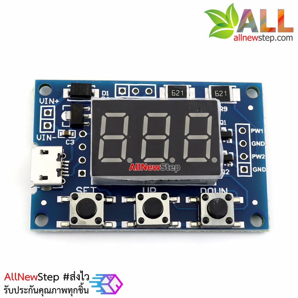

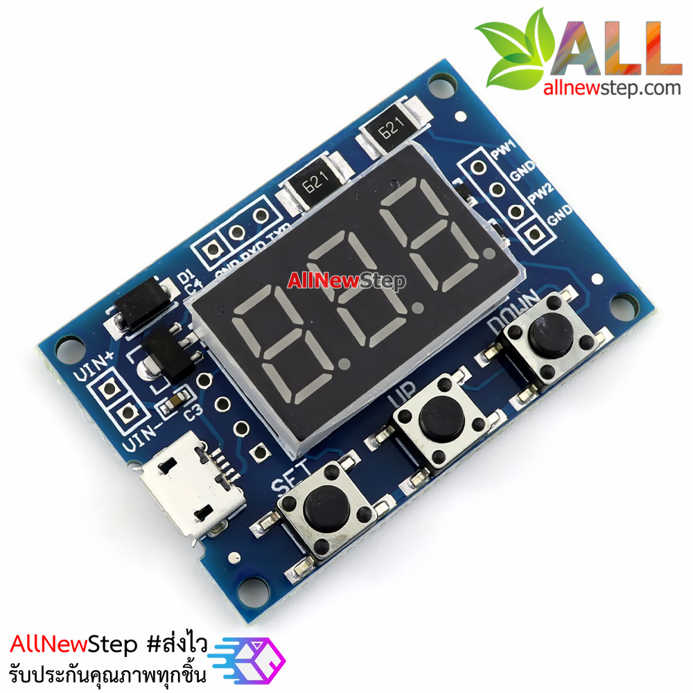
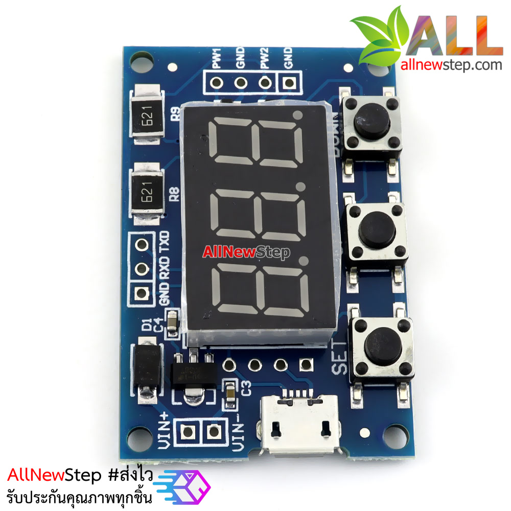


2-channel PWM pulse frequency duty cycle adjustable module square wave rectangular wave signal generator stepper motor driver
Module highlights:
1. Two independent PWM outputs, which can set the frequency and duty cycle separately;
2. Wide frequency range and high accuracy;
3.Can serial communication
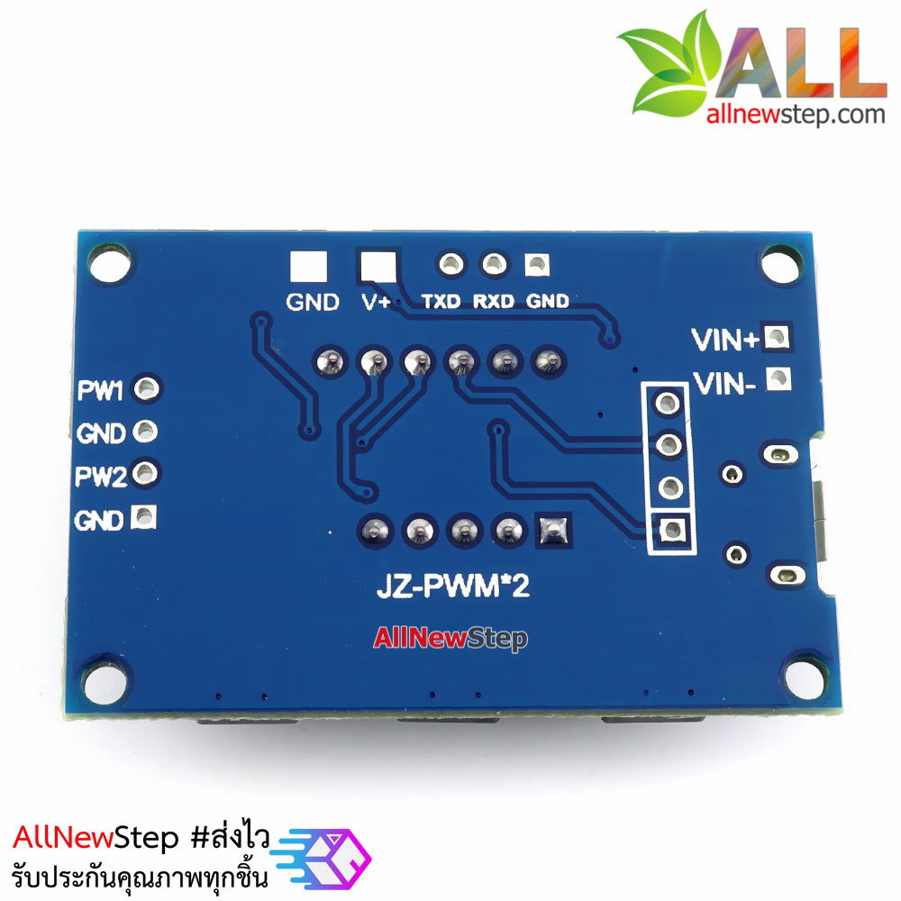
Dimensions: 41 * 28mm thickness: 1.6mm
Module description
Two independent PWM outputs, which can set the frequency and duty cycle separately;
It is divided into three frequency ranges :
1. XXX ( no decimal point ) : The minimum unit is 1Hz , and the value range is 1Hz ~ 999Hz ;
2. XX.X (the decimal point is in ten digits ) : the minimum unit is 0.1Khz ; the value range is 0.1 K H z ~ 99.9K H z
3. XXX ( three digits have decimal points ) : the minimum unit is 1Khz ; the value range is 1K H z ~ 150K H z
eg frequency display: 100 represents a PWM output 100Hz pulse;
54.1 represents the pulse of PWM output 54.1K H z ;
1.2.4. Pulses representing 124K H z of PWM output
Duty cycle value range: 0 ~ 100 ;
The three frequency ranges share a duty cycle. All setting parameters are saved after power-off.
Parameter settings
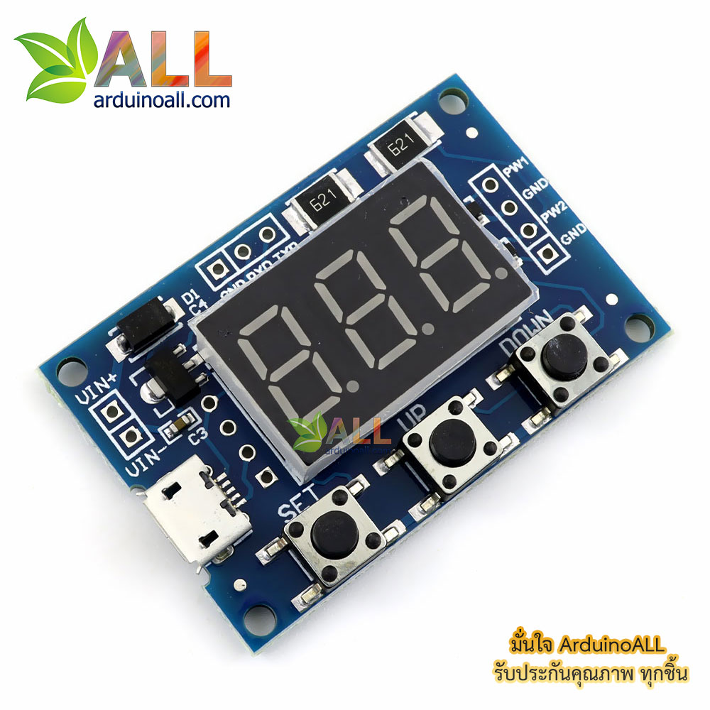
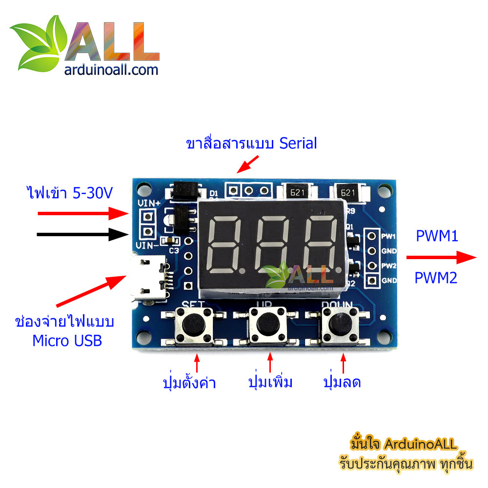
The module has 3 keys: Set , Up , Down ;
1. By short-pressing the [ Set ] key , four parameter values are displayed (FR1 : the frequency of PWM1 ; d U1 : the duty cycle of PWM1 ; FR2 : the frequency of PWM2 ; dU2 : the duty cycle of PWM2 ) , there will be corresponding before switching The parameter name flashes.
2. Directly press the [ Up ] and [ Down ] keys to modify the current parameter value ( long press to increase or decrease quickly).
3. The two PWMs each have 3 preset frequency values. In this frequency display interface, press and hold the [ SET ] key once to switch. The duty ratios of the 3 types of frequencies are the same . ( XXX: range 1Hz ~ 999Hz ; XX.X : the range of 0.1 Khz ~ 99.9Khz ; XXX : range 1Khz ~ 150 Khz , ) .
Module parameters:
1. Working voltage: 5--30V supports micro USB 5.0V power supply;
2. Frequency range: 1Hz ~ 150KHz ;
3. Frequency accuracy: The accuracy in each range is about 2% ;
4. Signal load capacity: output current can be about 8-30ma ;
5. Output amplitude: 5V V-pp by default (can be changed by external power supply);
6. Ambient temperature: -30 ~ + 70 ℃.
Fourth, the scope of application:
1. Used as a square wave signal generator to generate square wave signals for experimental development;
2. Used to generate a square wave signal that drives a stepper motor driver;
3. Generate adjustable pulses for MCU use;
4. Generate adjustable pulses and control related circuits (such as PWM dimming and speed regulation).
Five , serial control
Communication standard : 9600 bps
Data bits : 8
Stop bits : 1
Parity bit : none
Flow control : none
1, set the PWM frequency
“ S1FXXXT ” : Set the frequency of PWM1 to XXX HZ ( 00 1 ~ 999)
" S1FXX.XT " : setting PWM1 frequency of XX.X KHZ ( 00. . 1 ~ 99 . . 9)
" S1F: XXXT " : setting PWM1 frequency of XXX KHZ ( 0.0. . 1 . ~. 1 . . 5 . 0 . )
' S 1 ' : PWM1
' S 2 ' : PWM2
' F ' : frequency
' D ' : Duty cycle
' T ' is the end flag
2, set PWM duty cycle
“ S1DXXXT ” : Set the duty ratio of PWM1 to XXX ; ( 00 1 ~ 100)
“ S2DXXXT ” : Set the duty cycle of PWM2 to XXX ; ( 00 1 ~ 100)
Set successfully return: DOWN ;
Setting failed returns: FALL .